The Armada Power Optimizer™
Electric Water Heater Installation Guide
Welcome
Thanks for purchasing the Armada Power Optimizer.™ We’re excited to help you turn your electric water heater into one of the smartest appliances in your home.
Please read the Safety Considerations and all instructions in this Installation Guide carefully before installing the Armada Power Optimizer™.
The Optimizer™ is meant to be installed on an electric water heater over 240 volts and no greater than 5500 watts. The easiest way to determine what type of water heater you have is to refer to the manufacturer’s wiring diagram, which is generally found on the water heater or under one of the element access cover plates.
Important Reminder
If you have any questions or feedback about your Armada Power Optimizer’s™ compatibility, wiring, installation, or configuration, we’re here for you! Email install-support@armadapower.com or call toll-free 1 (855) 820-7500. Scroll down for installation instructions and troubleshooting information.
Before You Get Started

What's in the Box
- 1x The Armada Power Optimizer
- 2x Temperature Sensors (Thermistors)
- 2x Temperature Sensor Sleeves (Thermistor Sleeves)
- 3x Set Screw Wire Connectors
- 1x Lever Nut Wire Connector
- 1x Plastic Snap-in Bushing
- 2x #8 – 1/2” Self-Drilling Sheet Metal Screws
- 6x 4” Zip Ties
- 6x Zip Tie Mounts
- 2x Adhesive Strips
- 1x Leak Sensor (if purchased)
What You'll Need
- A Set of Screwdrivers
- A Hex Nut Driver
- Channel-lock Pliers
- A 3/32 Allen Wrench
- A Voltmeter or AC Line Tester
- Wire Cutters and Wire Strippers
- Needle Nose Pliers
- Drill or Impact Driver with
the Appropriate Bits
For Your Safety
Read these Safety Considerations and all instructions in this Installation Guide carefully before installing the Armada Power Optimizer™. If you have questions or require technical support contact Armada Power before initiating the installation.
Safety Considerations
- Installation of this device requires handling of high voltage wires.
- Installation must be made in strict compliance with the instructions and procedures outlined in this Installation Guide.
- Installation must be made in compliance with all applicable Local and/or National Electrical Codes, Building Codes, and Utility Requirements.
- The installation should be entrusted to duly qualified personnel where required by law.
- Ensure all equipment used in the installation is in good working order and observe all safety requirements attendant to the equipment being used.
- To avoid personal injury or death, turn off your circuit breaker and follow the proper safety precautions before proceeding.
- De-energize the water tank before beginning work.
Unsure about handling electrical wiring? Consult a qualified electrician.
*By attempting to install or otherwise use the Armada Power Optimizer™ you agree to release, indemnify, and hold harmless Armada Power from any claims or liabilities arising out of or in connection with your failure to adhere strictly to the requirements, procedures and/or safety recommendations set forth herein and/or from any negligent act or omission in connection therewith.
Section 1 – Disconnect Power & Inspect Tank
Proceed with caution and ensure all safety measures are in place before beginning the installation of the Armada Power Optimizer™. Turn off all power before initiating any electrical installation.
Directions:
- Thoroughly inspect the site for damage, leaks, or excessive corrosion. Do not continue with the installation if you see damage to the water heater, the electrical service, or the surrounding area.
- Locate the main electrical panel and identify the specific circuit breaker that supplies power to the water heater.
- Shut off power to the water heater by switching the appropriate circuit breaker to the off position (Figure 1).
- Use a multimeter or voltage sensor to confirm that the power supply to the water heater has been fully disconnected.
- Safely unwire the tank at the electrical cover on the top of the tank, following all guidelines to avoid any electrical hazards (Figure 2).
Click Images to Enlarge

Figure 1 – Electrical Panel

Figure 2 – Unwire the Tank
If you are unable to confidently identify the water heater circuit breaker or are unsure if the power to the water heater is off, stop work and call an electrician to complete the installation.
Section 2 | Optimizer™ Mounting
Ensure you have completed Section 1 and that the power supply to the water heater has been fully disconnected.
Preferred Method (Tank Top)
Directions:
- Remove the Optimizer™ cover by removing the top screw and sliding the plastic shell from the metal base (Figure 3).
- Remove the knock-out in the back of the Optimizer™. Insert a plastic bushing into the hole to prevent damage to the wire insulation (Figure 4).
- Position the Optimizer™ over the water heater wiring compartment. Ensure that the Optimizer™ completely covers this area.
- Push the wires coming from the top of the tank up through the bushing. It’s important that the bushing is present so that the wires don’t get damaged.
- Determine the appropriate knockout location to route the power source wires and remove that knockout from the Optimizer’s™ sheet metal base.
- With the Optimizer™ in place over the wiring compartment, install the two self-tapping screws through any of the provided mounting holes (Figure 5) to secure the device to the hot water tank.
Click Images to Enlarge

Figure 3 – Cover Screw

Figure 4 – Bushing Placement

Figure 5 – Tank Mounting Holes
Alternate Method (Wall or Other Surface)
Directions:
It is sometimes advantageous to mount the Optimizer™ on a nearby wall or other surface due to clearance issues on top of the tank. **This will require an extra length of conduit or cable to be installed in accordance with local electrical code.**
- Remove the Optimizer™ cover by removing the top screw and sliding the plastic shell from the metal base (Figure 6).
- Position the Optimizer™ where desired, keeping in mind that it must be placed within 6 feet of the farthest heating element on the tank, as the Temperature Sensors (Thermistors) are 6 feet long.
- While holding the Optimizer™ in place mark the location of the screw holes indicated in (Figure 7).
- Determine which 2 knockouts will be used (one for the source conduit/cable and one for conduit/cable to the tank). Remove the 2 knockouts from the Optimizer™ sheet metal base (Figure 8).
- Secure the Optimizer™ with the two self-tapping screws.
Click Images to Enlarge

Figure 6 – Cover Screw

Figure 7 – Alternative Mounting Holes

Figure 8 – Knockout Options
Section 3 | Sensor Connection & Lug Verification
Directions:
- Connect the Leak Sensor to the leak sensor port (Figure 9 and Figure 11 #1).
- Connect both Temperature Sensors (Thermistors) to the temperature sensor ports (Figure 10 and Figure 11 #2).
- There are two slots on each side of the metal base (Figure 12). Slide the groove on each Temperature Sensor (Thermistor) strain relief into a strain relief slot and check for proper placement.
- Proper placement will resemble (Figure 13).
- Carefully place the sensor wires out of the way while you complete the remainder of the installation.
Click Images to Enlarge

Figure 9 – Leak Sensor

Figure 10 – Temperature Sensors and Sleeves

Figure 11 – Port Locations

Figure 12 – Strain Relief Slots

Figure 13 – Leak Sensor
Section 4 | Wiring
Do you have a Single-Phase or a 3-Phase water heater?
The LCS2400 Optimizer™ is intended to operate on any single-phase (120V, 208V, 240V) dual or single-element water heater rated 5500W or less. The Optimizer™ is also compatible with 3-phase water heaters wired for non-simultaneous single-phase operation. The easiest way to determine what type of water heater the Optimizer™ is being installed on is to refer to the manufacturer’s wiring diagram, which is generally found on a sticker on the outside of the water heater or under one of the element access cover plates. Single-Phase units are typically similar to (Figure 14), 3-Phase units are typically similar to (Figure 15).
Click Images to Enlarge
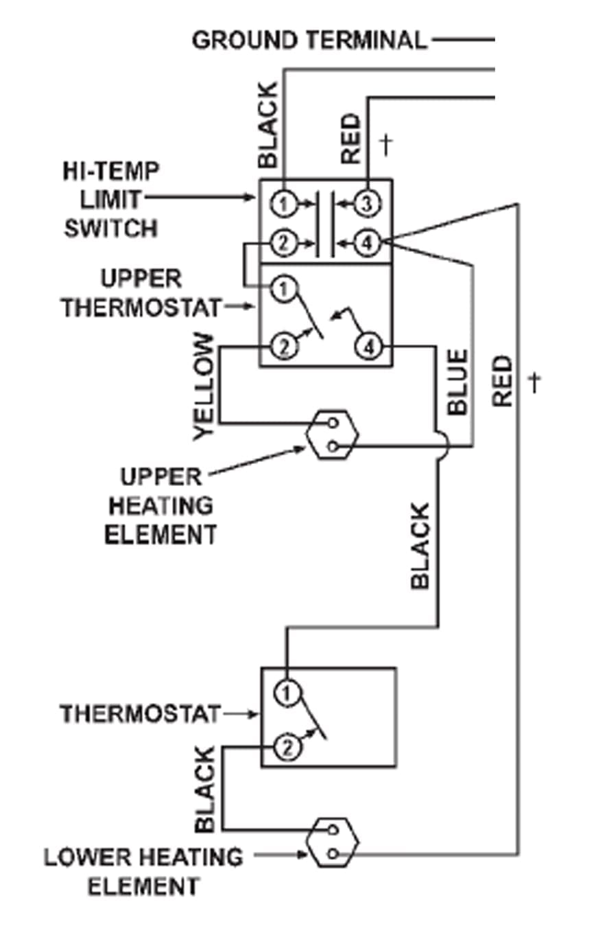
Figure 14 – Single-Phase Example
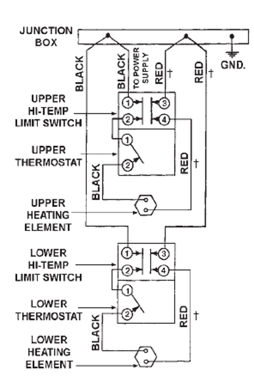
Figure 15 – 3-Phase Example
Directions:
2-Wire Source NO Red Wire (120V / 208V / 240V Single-Phase Tank)
- Push the source power cable through the hole previously punched out and secure it with the lever nut wire connector.
- Connect the power wiring as shown in (Figure 16).
- Once the wires are connected, give them a final check to ensure that the insulation is not cut and that the wires are properly secured in the wire connectors.
- With the breaker still in the off position, use a multimeter in resistance mode and verify that there are no short circuits between any of the terminals of the Optimizer™ and ground.
Click Image to Enlarge
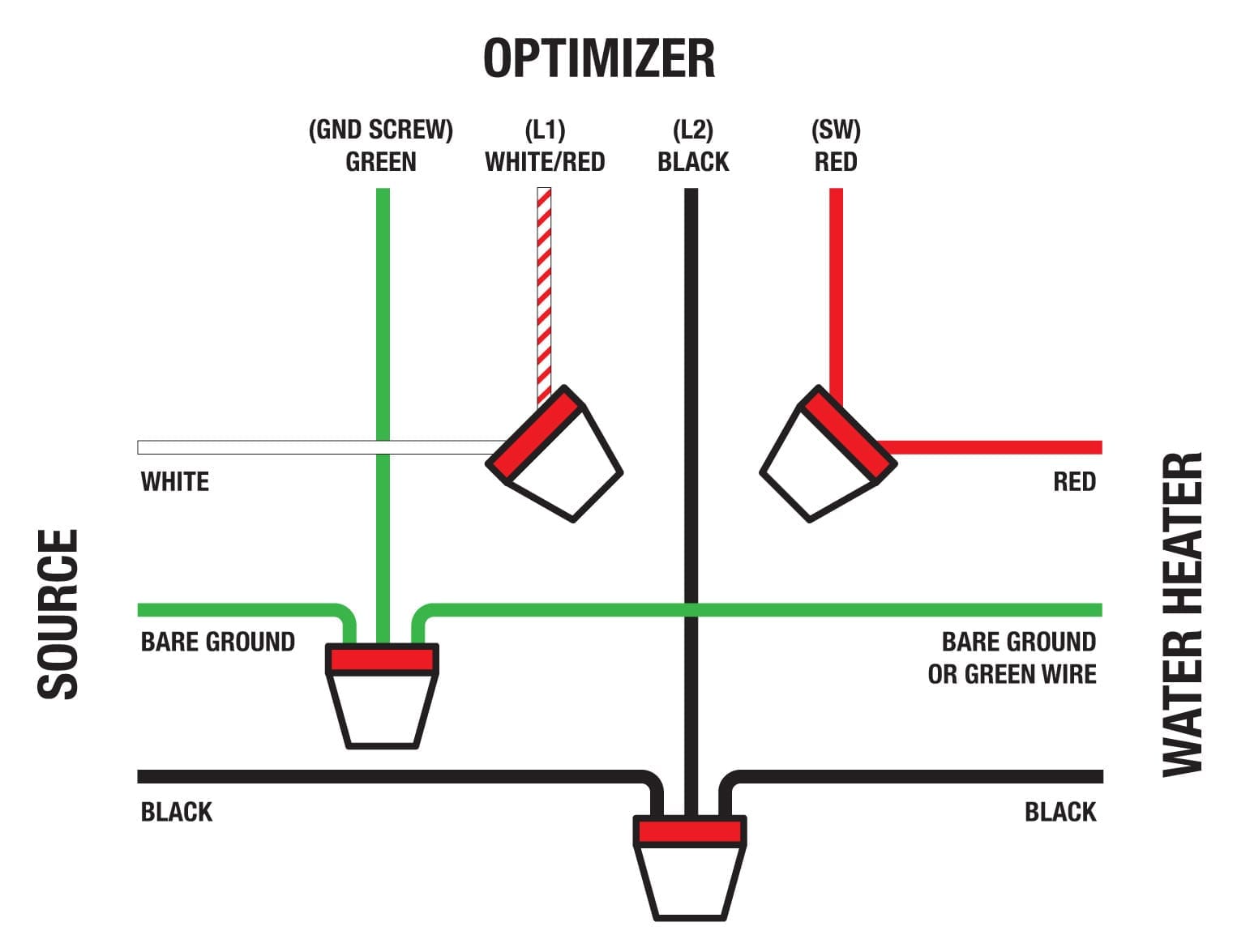
Figure 16 – 2-Wire Source Diagram (Single-Phase Tank)
Directions:
2-Wire Source WITH Red Wire (120V / 208V / 240V Single-Phase Tank)
- Push the source power cable through the hole previously punched out and secure it with the lever nut wire connectors.
- Connect the power wiring as shown in (Figure 17).
- Once the wires are connected, give them a final check to ensure that the insulation is not cut and that the wires are properly secured in the lever nut connectors.
- With the breaker still in the off position, use a multimeter in resistance mode and verify that there are no short circuits between any of the terminals of the Optimizer™ and ground.
Click Image to Enlarge
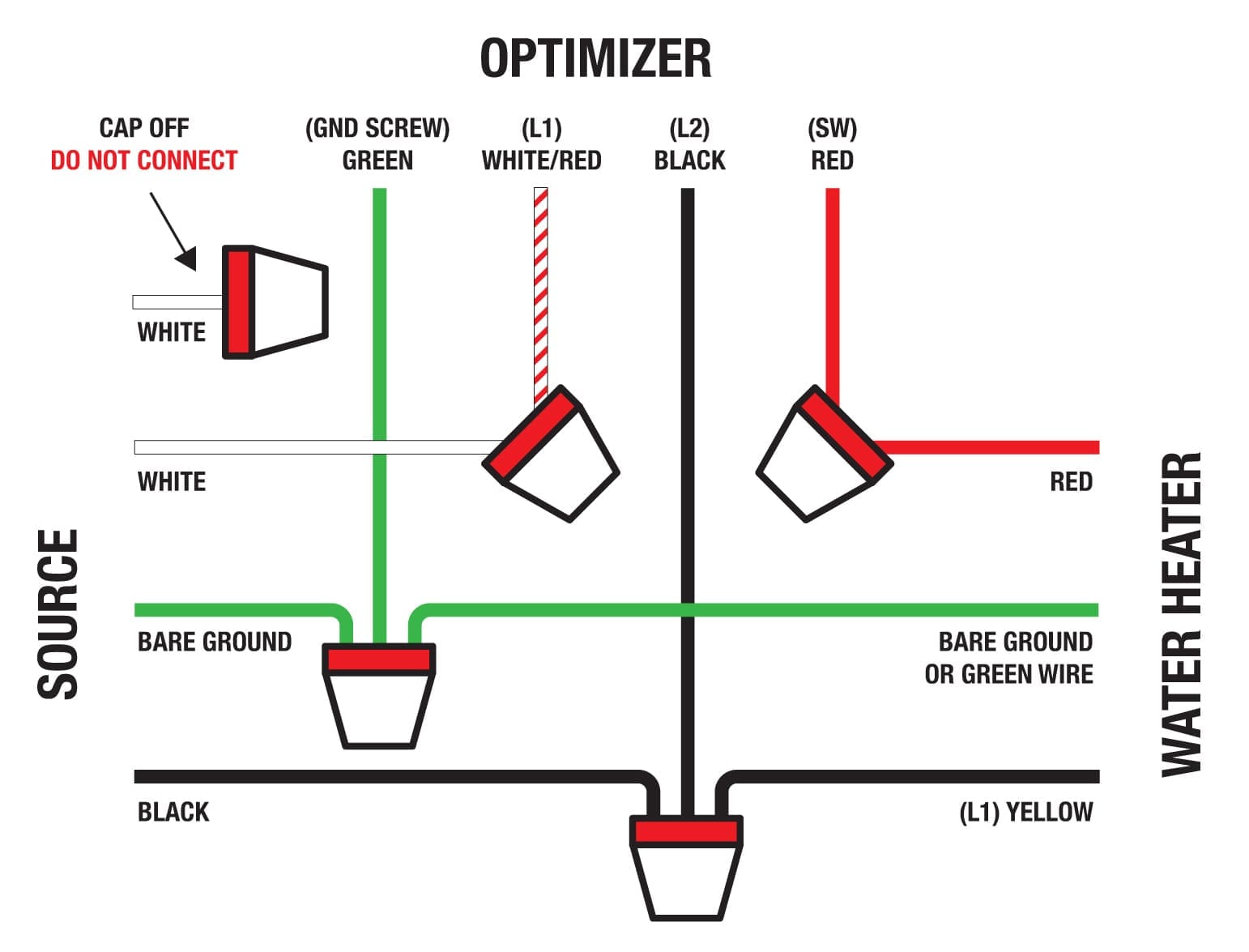
Figure 17 – 2-Wire Source Diagram (Single-Phase Tank)
Directions:
3-Wire Source NO Red Wire (3-Phase Tank)
- Push the source power cable through the hole previously punched out and secure it with the lever nut wire connectors.
- Connect the power wiring as shown in (Figure 18).
- Once the wires are connected, give them a final check to ensure that the insulation is not cut and that the wires are properly secured in the lever nut connectors.
- With the breaker still in the off position, use a multimeter in resistance mode and verify that there are no short circuits between any of the terminals of the Optimizer™ and ground.
**The tank wire colors in (Figure 18) are an example based on the wiring diagram provided in (Figure 15). It is important to verify the wire color on the manufacturer’s diagram before proceeding, as color can be manufacturer-specific.**
Click Image to Enlarge
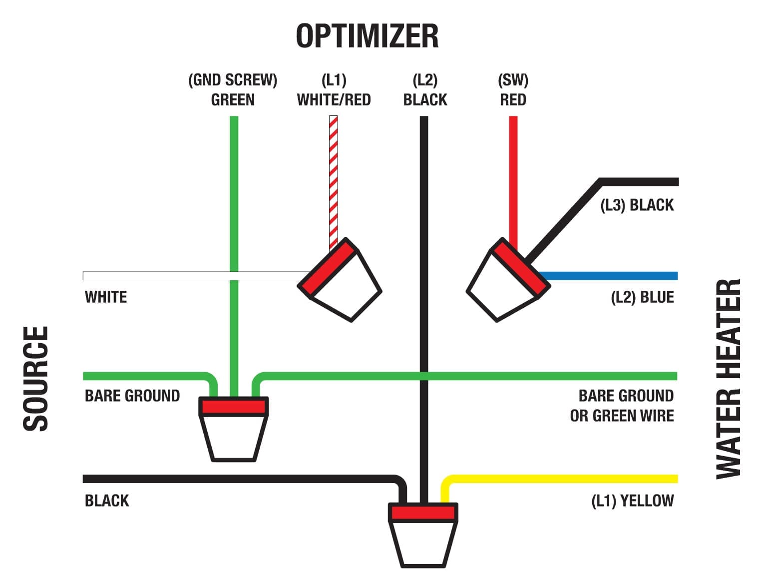
Figure 18 – 3-Wire Source Diagram (3-Phase Tank)
Directions:
Figure 19 – 3-Wire Source Diagram (3-Phase Tank)
- Push the source power cable through the hole previously punched out and secure it with the lever nut wire connectors.
- Connect the power wiring as shown in (Figure 19).
- Once the wires are connected, give them a final check to ensure that the insulation is not cut and that the wires are properly secured in the lever nut connectors.
- With the breaker still in the off position, use a multimeter in resistance mode and verify that there are no short circuits between any of the terminals of the Optimizer™ and ground.
**The tank wire colors in (Figure 19) are an example based on the wiring diagram provided in (Figure 15). It is important to verify the wire color on the manufacturer’s diagram before proceeding, as color can be manufacturer-specific.**
Click Image to Enlarge
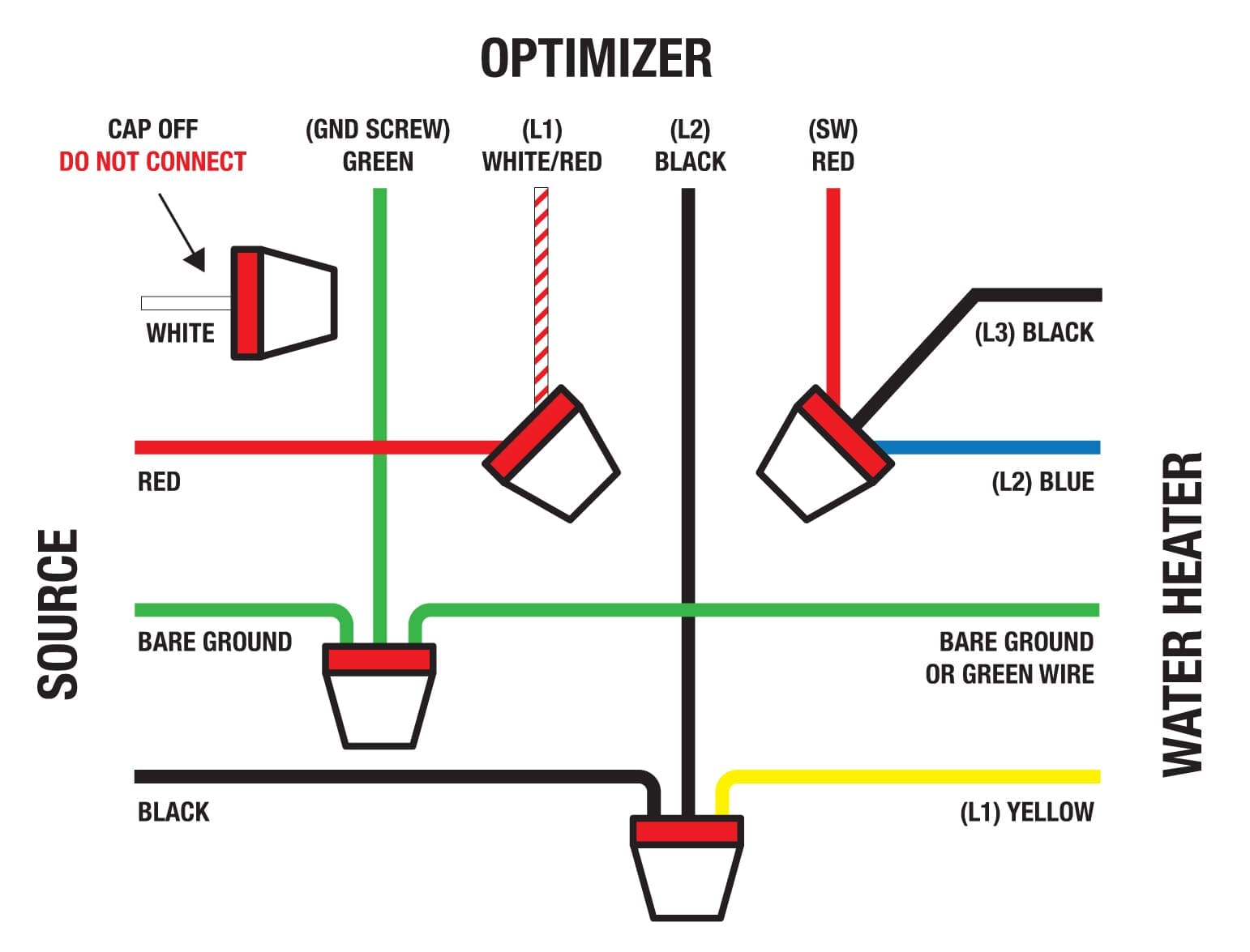
Figure 19 – 3-Wire Source Diagram (3-Phase Tank)
Section 5 | Securing the Top Cover
Directions:
- Before placing the top cover on the Optimizer™, use a 3/32 Allen wrench to verify the terminal lug screws are tight. You will access these screws through the terminal lug access holes in the circuit board cover (Figure 20).
- Locate the breakaway tabs that need to be removed to allow clearance for the sensor strain relief. One tab is on each side of the Optimizer™ cover (Figure 21).
- Break off the necessary tabs with a pair of pliers (Figure 21).
- Place the cover on top of the metal shell and slide it forward until the front and rear tabs are fully seated (Figure 22, Figure 23).
- Once the tabs are seated, the top screw can be reinserted, securing the cover in place.
Click Images to Enlarge

Figure 20 – Tighten Terminal Lug Screws

Figure 21 – Breakaway Tabs

Figure 22 – Rear Tabs

Figure 23 – Front Tabs

Figure 24 – Tighten Top Screw
Section 6 | Sensor Placement
Thermistors
Only Use the Temperature Sensors (Thermistors) Supplied with the Optimizer™
Directions:
- Remove the bottom and top element access panels (Figure 25).
- Slide the protection sleeve over the end of each Temperature Sensor (Thermistor) wire (Figure 26).
- Apply the adhesive strip to the probe end (Figure 27).
- Identify mounting locations for the Temperature Sensors (Thermistors). They must be placed in contact with the internal bare metal tank as close to the thermostat as possible in each access panel (Figure 28). If physical contact to the tank is not possible then they may be placed on the thermostat/element metal mounting bracket. They should never be left unsecured in open air.
- Only one Temperature Sensor (Thermistor) should be routed to each access hatch: one for the top and one for the bottom.
- In the rare instance that the water heater has only a single element, one Temperature Sensor (Thermistor) should be placed on the hot water output pipe as close to the tank as possible.
Click Images to Enlarge

Figure 25 – Access Panels

Figure 26 – Protection Sleeve

Figure 27 – Adhesive Strip
")
Figure 28 – Mounting Leak Sensor (Thermistors)
Leak Sensor
Only Use the Leak Sensor Supplied with the Optimizer™
Directions:
- Place the Leak Sensor (not the wire) in the leak tray at the bottom of the tank. If there is no tray, the sensor can be coiled around the bottom of the tank itself (Figure 29).
- Reinstall the upper and lower element access panels, replace any removed insulation, and ensure the wire protection sleeves cover the wires where the covers meets the tank. This ensures the sharp edge of the hatch cover won’t cut the thermistor wire (Figure 30).
- Run the Temperature Sensor (Thermistor) and Leak Sensor wires neatly up the side of the tank, securing them with the zip ties and self-adhesive mounts
(Figure 31). - Coil up the excess wire, secure it with a zip-tie, and place it next to the Optimizer™ on top of the tank
(Figure 31).
Click Images to Enlarge

Figure 29 – Leak Sensor

Figure 30 – Access Panels

Figure 31 – Excess Wires
Section 7 | Final Steps
Directions:
- Re-energize the breaker. If the breaker panel is near the water heater, you should hear an audible click from the Optimizer™ as the relay is energized.
- At the same access panel where you tested, the power was off, use the multimeter or contactless voltage detector to verify that power has been restored to the water heater.
- Reinstall the upper element access panel, making sure any removed insulation is put back in and that the wire protection sleeve covers the wires where the cover meets the tank. This ensures that the sharp edge of the hatch cover does not cut the thermistor wire.
- The Optimizer™ is now ready for network communications set-up.
Click Image to Enlarge

Section 8 | Communication Configurations

Figure 32 – Armada Power Mobile App
Directions:
- Have your home Wi-Fi password handy.
- Search for the Armada Power App in the App Store or on Google Play.
- Install the App on your mobile device and open it.
- Tap the “Sign Up” Button on the home screen
(Figure 32). - Follow all of the steps in the Armada Power Quick Start Guide included with this device, or use the links below.
Setting Up Your Armada Power Optimizer
Don’t wait! It takes only minutes to start enjoying the benefits of your home’s newest smart appliance. Follow these simple steps to connect the Armada Power Optimizer™.